| For standard configurations | For customized configurations | ||
| Limitations | Capacity | up to 18 t/h | up to 24 t/h |
| Pressure in receiver | up to 0,5 barg | ||
| Backpressure in condensate line | up to 8 barg | ||
| Motive steam pressure* | up to 12,8 barg | up to 19 barg | |
* For high motive steam pressure, the recommended configuration is DCHm-BRV, with a motive steam pressure reducing valve. See section “Selection and installation details”.
Materials
| For standard configurations | For customized configurations | |
| Condensate pump | SG Iron | Determined based on the Questionnaire information |
| Stop valves, strainers and filters, float steam traps | Cast iron | |
| Thermodynamic steam traps, pipeline connectors | Stainless steel | |
| Motive steam pressure reducing valve | SG Iron | |
| Check valves | Stainless steel, brass | |
| Steam pipelines | Carbon steel* | |
| Receiver, condensate pipelines | Carbon steel* | |
| Frame | Carbon steel* | |
* By default. Other materials can be quoted in “Other requirements” section of the Questionnaire.
Configuration types
Motive steam pressure reduction
|
|
|
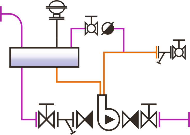
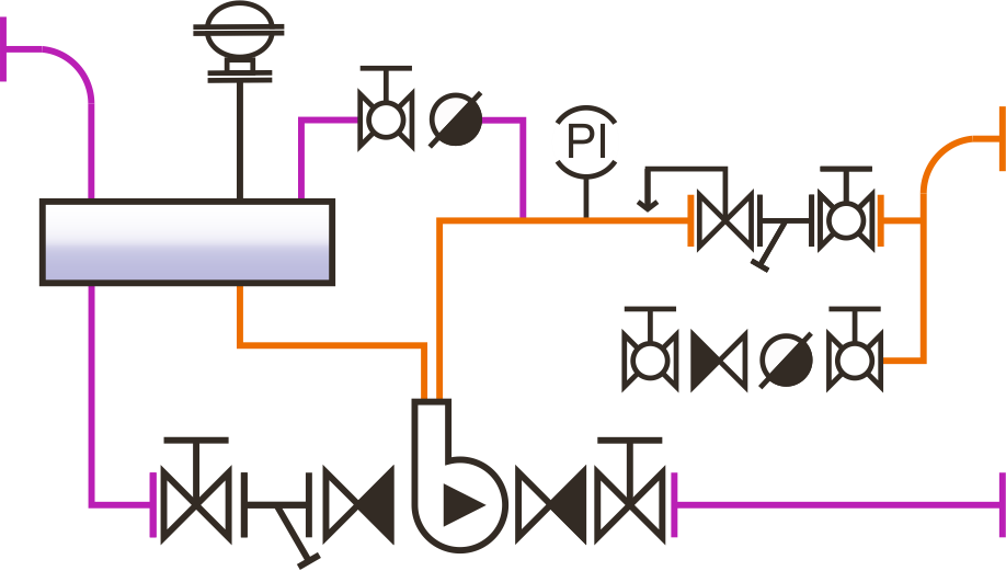
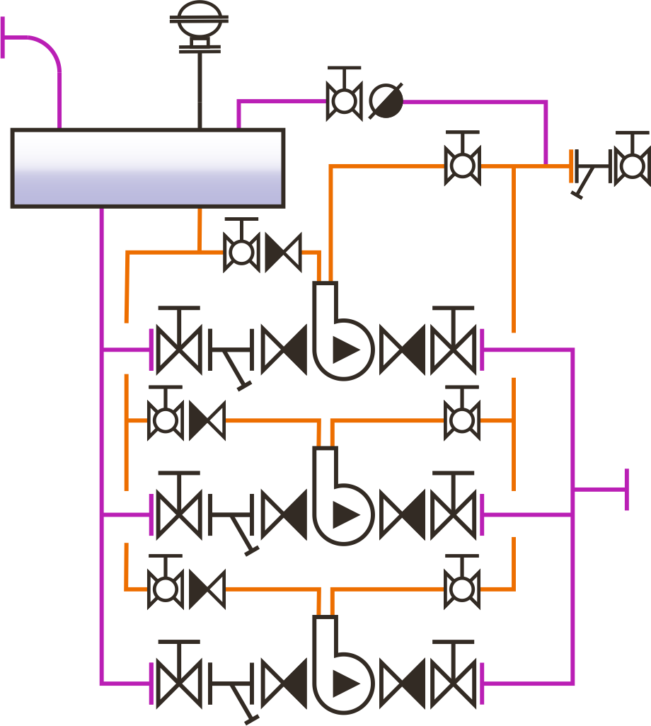
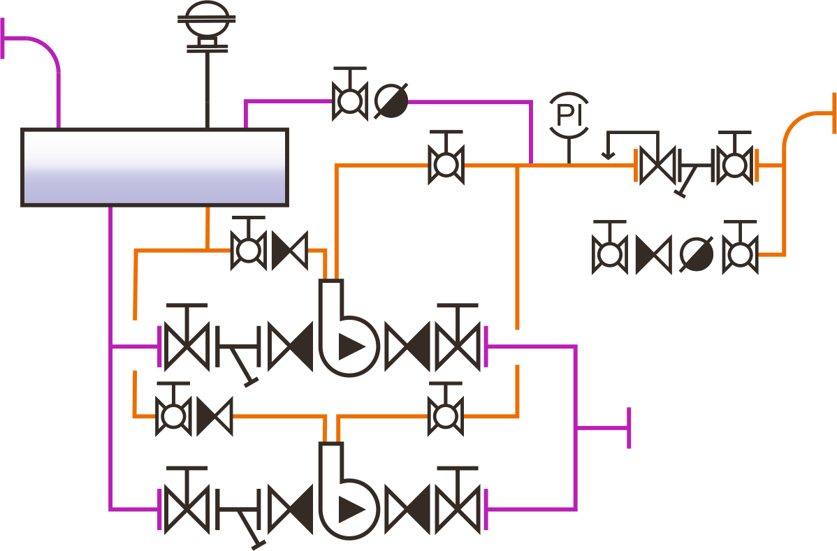
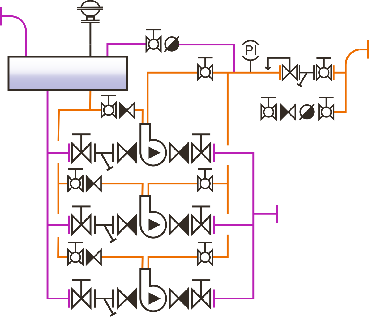
| DCHm is a unit with a motive steam delivery line, containing a stop valve, a strainer and a steam trapping unit | DCHm-BRV is a unit with a motive steam delivery line fitted with a pressure reducing valve. |
Supplied types:
| Name | Description | Capacity* |
| DCHm-50S DCHm-50S-BRV |
Unit with one pump DN50хDN50 | Up to 4 t/h |
| DCHm-80S DCHm-80S-BRV |
Unit with one pump DN80хDN50 | Up to 6 t/h |
| DCHm-80D DCHm-80D-BRV |
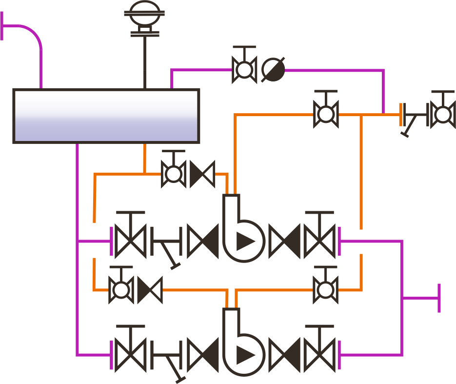
Unit with two pumps DN80хDN50 | Up to 12 t/h |
| DCHm-80T DCHm-80T-BRV |
Unit with three pumps DN80хDN50 | Up to 18 t/h |
Layout
|
|
|
|
| DCHm-..S — unit with one mechanical pump | DCHm-..D — unit with two mechanical pumps | DCHm-..T — unit with three mechanical pumps |
|
|
|
|
| DCHm-..S-BRV — unit with one mechanical pump and a motive steam pressure reducing valve | DCHm-..D-BRV — unit with two mechanical pumps and a motive steam pressure reducing valve | DCHm-..T-BRV — unit with three mechanical pumps and a motive steam pressure reducing valve |
* The installation capacity depends on several factors, including motive steam pressure and full backpressure in the condensate line. See “Selection and installation details”.
Dimensions and weight of customized configurations
Custom-shaped for each order based on the information provided in the Questionnaire. For more information, contact Steam Control Engineering, LLC (OOO).
Dimensions and weight of standard configurations (approximate)*
| TYPE | Model | Steam flow rate, max (kg/h) |
Water flow rate, Δt=20°C
(m3/h) |
Height, H (mm) |
Length, L (mm) |
Width, B (mm) |
Connection | |||
| Steam | Condensate | Water | ||||||||
| Inlet, А (mm) |
Outlet, Б (mm) |
Inlet, В (mm) |
Outlet, Г (mm) |
|||||||
| TYPE | Model | Weight,kg | c1,mm | c2,mm | d1,mm | d2,mm | е1,mm | е2,mm | f1,mm | k,mm |
* The actual unit may have slightly different appearance than the types shown in the figure below, but the stated dimensions will remain unchanged. For more information, contact Steam Control Engineering, LLC (OOO)..
Selection and installation details
| A proper condensate recovery unit design is to be made in accordance with local regulations prior to a condensate recovery unit installation. All necessary additional pipeline ancillaries, safety and control devices are to be included in order to ensure safe and long-term operation of equipment. |
| It is not allowed to connect pressurized (pumped) condensate lines downstream mechanical pumps into trap discharging (non-pumped) condensate lines as well as into constant static pressure lines (downstream electrical pumps). The best option would be having pressurized condensate return lines installed downstream of mechanical pumps separately coming into vented condensate tanks. |
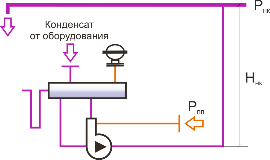
| Total backpressure in a pressurized condensate line (lift Hcc + condensate line pressure Pcc) must be less than the motive steam pressure or compressed air pressure Pms to achieve the target capacity. Optimal motive steam pressure should be 2-4 barg above the total backpressure in the condensate line. If this ratio is significantly exceeded, in order to extend the service life of pumps, the configuration with a pressure reducing valve BRV must be selected. In customized configurations, motive steam lines can be fitted with a safety valve, which increases the inlet motive steam pressure at the reducing valve up to 19 barg.
|
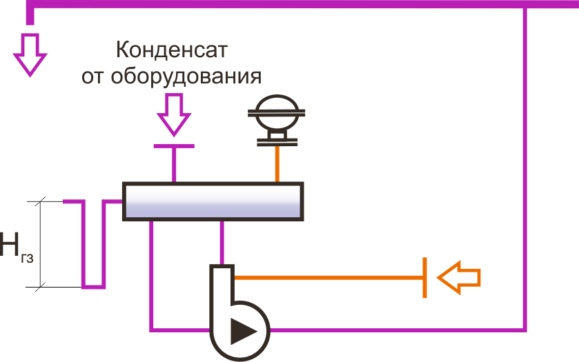
| An overflow pipeline with a water seal is to be fitted on the receiver to ensure the condensate drainage to a safe place in the event of pump or system malfunction. The overflow pipeline must be a ’U’ bend water seal which has a depth of Hws =0.5-1 m. The nominal diameter of an overflow pipeline must be no less than the nominal diameter of the respective connection located on the receiver.
|
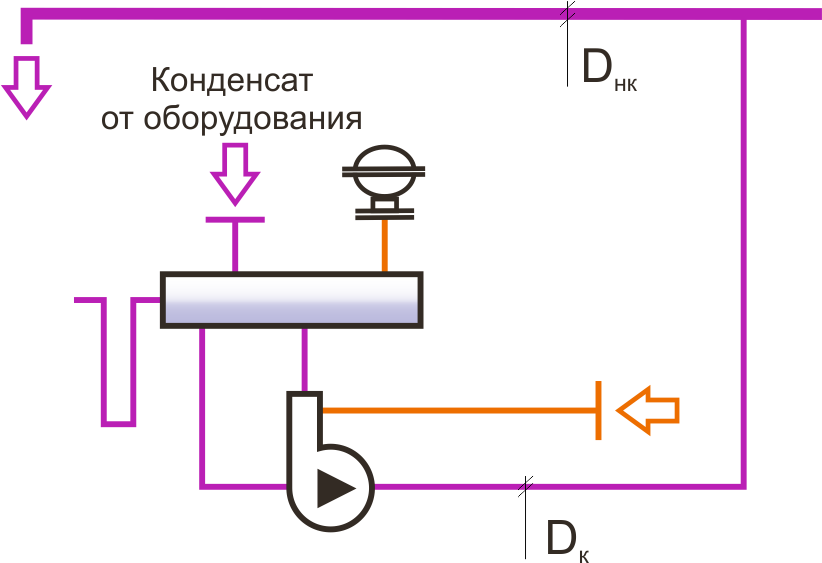
| The diameter of the pipeline connecting the single unit and the common condensate return line Dc, can be selected based on the flow rate, which is a 6-fold maximum flow rate under the specified motive steam pressure and total backpressure in a pressurized condensate line for one pump, multiplied by the factor 6, but in any case should not be less than the diameter of the fitting pipe at the unit outlet. The diameter of the common condensate return line Dcc, if there are more than one condensate recovery units, is determined by the hydraulic calculation based on the number and performance of the connected units.
For more information, contact Steam Control Engineering, LLC (OOO). |
| The vent pipe must have no areas where condensation could occur. The vent pipe diameter must be not less than the diameter of the corresponding connection on the receiver. |
| Flash steam is separated in the receiver and vented to atmosphere through the vent pipe. For flash steam recovery, installation of an exhaust vapour condenser should be considered. |
| Optionally, the unit can be equipped with a condensate quality control system able to perform constant monitoring of impurities dissolved in the condensate, such as acids, alkalis, etc., redirecting contaminated condensate to waste and protecting boilers and a condensate system. For more information, contact Steam Control Engineering, LLC (OOO). |
| For condensate recovery units with a vented receiver, it is highly recommended to have trap discharging (non-pumped) condensate lines the equipment located above the receiver level aligned with the constant slope without lifts in the direction of the receiver. In this case, condensate flows in the receiver by gravity without creating backpressure at the outlet of the steam-using equipment. If, however, it is not possible to avoid lifting of the non-pumped condensate return lines, the lift should be minimized, and check valves should be installed to stop condensate falling back down to the traps. |
| If the unit is installed outdoors, pumps can be supplied with automatic drain valves to remove condensate from any low points (thermostatic steam traps of special design. If the unit needs such protection device, please, indicate this in the “Other requirements” column in the “Questionnaire”. |
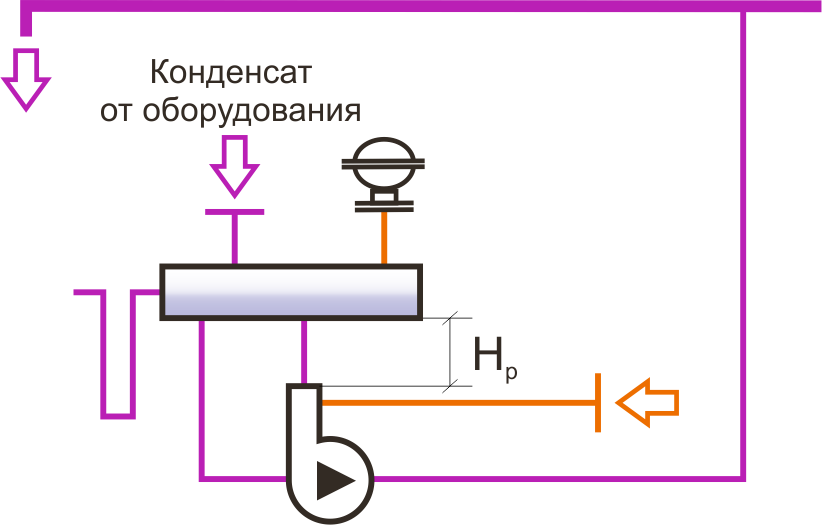
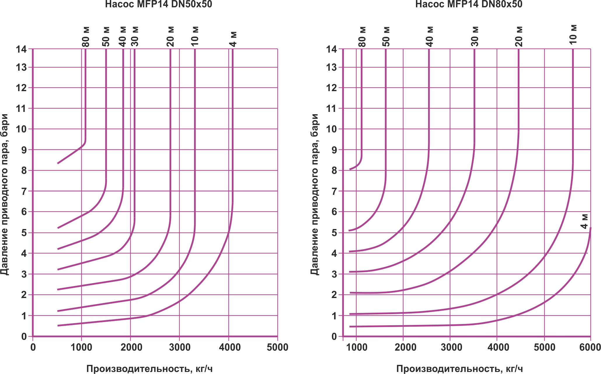
| The unit capacity (kg/h of condensate being pumped) depends on several factors, in particular, on the motive steam pressure, total backpressure in the condensate line and the filling head (the height at which the receiver is installed). Below you can find capacity charts of single pumps DN50x80 and DN80x80 which can be used to determine the capacity of units in the “List of standard configurations”, and to calculate the diameter of the pressurized condensate return line. The charts are created based on value of a filling head Hr = 0,3 m (this value is taken into account in the design of models from the “List of standard configurations”) and saturated steam as a motive medium.
If compressed air is used as a motive fluid, the pump capacity will increase. For more information, contact Steam Control Engineering, LLC (OOO).
|