[[ swipeNote ]]
|
For customized configurations |
||
| Limitations | Capacity |
up to 50 t/h |
| Pressure in receiver |
up to 0,5 barg |
|
| Backpressure in condensate line |
up to 8 barg |
|
| Connection to the electricity grid |
Determined based on the Questionnaire information |
|
Materials
|
For customized configurations |
|
| Pumps |
Determined based on the Questionnaire information |
| Stop valves, strainers and filters | |
| Check valves | |
| Ball valves | |
| Butterfly valves | |
| Receiver |
Carbon steel* |
| Condensate pipelines |
Carbon steel* |
| Frame |
Carbon steel* |
* By default. Other materials can be quoted in “Other requirements” section of the Questionnaire.
Control system
- If a configuration without frequency converter has been selected: “on/off” control of condensate level in the receiver based on the signal from a discrete level sensor.
- If configuration DCHe -..- VFD has been selected: smooth control of the water level in the receiver based on the signal from the analogue level sensor.
- If configuration DCHe -..- VFD has been selected: pump operation control with error alarms generation.
- If configuration DCHe-DG-.. has been selected:
- automatic start of a backup pump if the working pump fails;
- automatic change of the master pump after a specified period of time;
- a backup pump may be connected for a short time to overcome peak loads.
- General alarm (dry contact) and optional configurable digital output.
- Digital input for remote on/off switching of the unit.
- On request: digital interface for connection with the top level of the Computerized Process Control System (CPCS) (Profinet, Modbus, Profibus).
Dimensions and weight of customized configurations
Custom-shaped for each order based on the information provided in the Questionnaire. For more information, contact Steam Control Engineering, LLC (OOO).
Selection and installation details
| A proper condensate recovery unit design is to be made in accordance with local regulations prior to a condensate recovery unit installation. All necessary additional pipeline ancillaries, safety and control devices are to be included in order to ensure safe and long-term operation of equipment. |
| It is not allowed to connect pressurized (pumped) condensate lines downstream electrical pumps into trap discharging (non-pumped) condensate lines as well as into pressurized condensate return lines (downstream mechanical pumps). The best option would be having pressurized condensate return lines installed downstream of electric pumps separately coming into vented condensate tanks or into deaerators. |
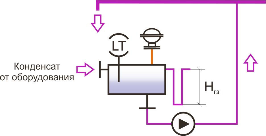
| During installation, attach the overflow pipeline fitted with a water seal which drains the condensate to a safe place, to the fitting pipe located on the receiver. Water seal should be located at a height Hws = 0,5-1 м. The nominal diameter of an overflow pipeline must be no less than the nominal diameter of the fitting pipe.
|
| The vest pipe must have no areas where condensation could occur. The vent pipe diameter must be not less than the diameter of the corresponding fitting pipe on the tank. |
| Flash steam is separated in the tank and vented to atmosphere through the vent pipe. For flash steam recovery, installation of a vent pipe on an exhaust vapour condenser should be considered. |
| Optionally, the unit can be equipped with a condensate quality control system for continuous monitoring of impurities dissolved in the condensate, such as acids, alkalis, etc., and to divert the flow of contaminated condensate, excluding its ingress into the boiler, and is also able to generate alarms. For more information, contact Steam Control Engineering, LLC (OOO). |
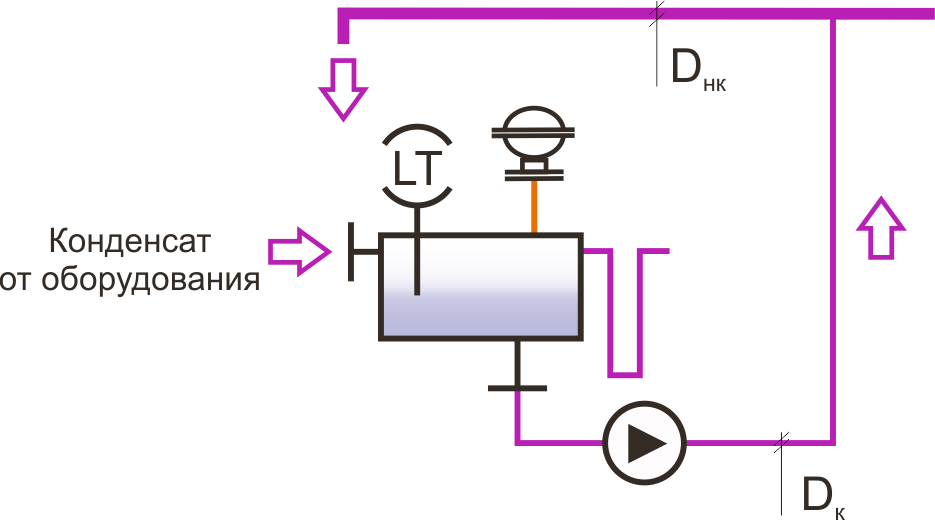
| The diameter of the pipeline connecting the single unit and the common condensate return line Dc, can be selected based on the flow rate, which is a 1.5-fold nominal flow rate of the condensate removed from the equipment, but in any case should not be less than the diameter of the fitting pipe at the unit outlet. The diameter of the common condensate return line Dcc, if there are more than one condensate recovery units, is determined by the hydraulic calculation based on the number and performance of the connected units.
For more information, contact Steam Control Engineering, LLC (OOO). |
| For condensate recovery units with a vented receiver, it is highly recommended to have condensate outlet fitting pipes of the equipment located above the receiver plane, and have unpressurized condensate return lines directed from steam traps without sloping in the direction of the receiver. In this case, condensate flows in the receiver by gravity without creating backpressure at the outlet of the steam-using equipment. If, however, lifting of the condensate return line downstream of the steam trap can not be avoided, the lift of the condensate return line should be minimized, and check valves should be installed in the steam trapping units. |